
Quick answer
Locate structural movement joints and obtain the project’s deflection criteria before finalising an operable wall track route. The wall supplier needs a supported path from the closed opening to the parking position, while the structural engineer determines support and movement requirements. If the proposed route crosses a movement joint, the responsible team must approve a project-specific detail. An installed-track photograph cannot prove that such a crossing is acceptable.
Read the building movement drawings first
An operable wall hangs from a track, so the building elements supporting that track are part of the design conversation. Ask for structural drawings that identify beams, slabs, movement joints and any expected relative movement near the full travel route. A ceiling finish plan is useful for coordination, but it may conceal the support conditions that matter here.
The project structural engineer should state the movement and deflection information needed by the selected partition system. The supplier then reviews how its track, carriers and panel clearances relate to those inputs. Do not copy a generic deflection allowance from another building or interpret an unlabelled line on a plan as a movement joint.
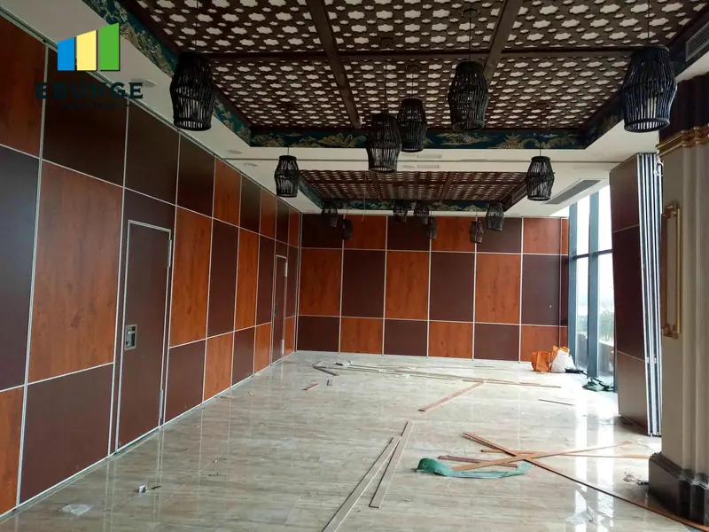
This genuine installed room shows a wood-look partition below a finished ceiling. It illustrates the visible relationship between wall and ceiling. The photograph does not reveal the structural members, design deflection or any concealed expansion joint.
Draw the whole supported route
A proposed wall layout should show the closed line, each turning point and the complete parking position. A straight portion may look simple while the route to the stack passes under a different support condition. Put the structural grid and movement-joint lines on the same drawing as the track. That overlay makes questions visible before the ceiling and support work are fixed.
If a joint lies near or across the planned path, treat it as a hold point. The engineer and supplier must establish whether a compatible route and connection detail can be designed for the selected system. The answer may change the track alignment or the parking strategy. An installer should not bridge the joint with a normal track section by assumption.
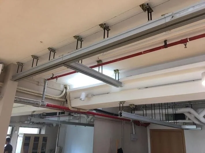
This first-party installation photograph shows a suspended aluminum track with visible support brackets and a turning branch. It helps explain why the support path must be drawn continuously. The photo does not disclose the load design, fixing approval or any engineered movement detail.
Keep the responsibilities distinct
The structural engineer defines the building support and allowable movements. The architect coordinates the ceiling and finish interfaces. The partition supplier returns system-specific track, carrier and panel information. The installer checks the approved site condition before fitting the track. Writing these responsibilities into the tender and submittal schedule prevents an unresolved gap from being passed between trades.
Any change in beam location, ceiling depth, partition height or parking position should trigger another review. Shop drawings need to identify assumptions as assumptions, with approval before fabrication. A supplier drawing is not a substitute for structural design, and a structural drawing alone does not select a compatible operable-wall track.
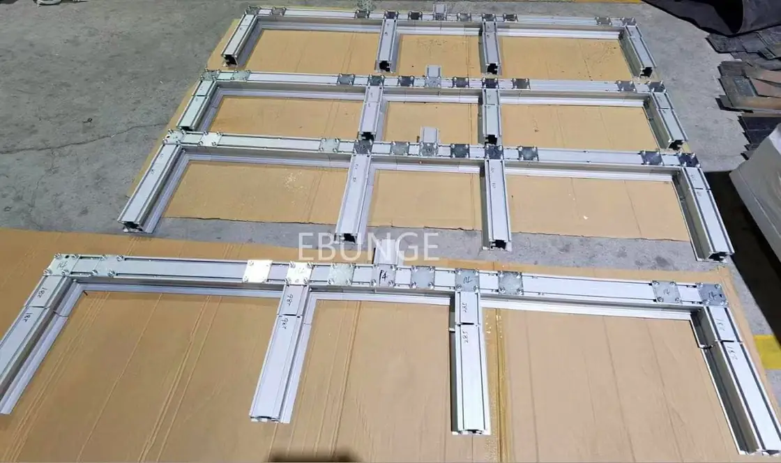
The real pre-shipment photograph shows marked aluminum track sections and junction pieces laid out together. It demonstrates that route components are project items to identify and check. Their appearance cannot establish a site-specific expansion-joint solution or installed support capacity.
Verify the approved condition on site
Before installation, compare the as-built support positions, ceiling level and opening with the approved drawings. Record deviations and return them to the responsible designers. During handover, move the panels through the full approved route and check that they park and close as intended. An operating test can reveal an obvious interference, but long-term structural movement still depends on the engineered detail and inspection plan.
Keep the final evidence together: structural criteria, selected-system drawings, approved support and any movement-joint detail, site inspection records and operating instructions. If no movement joint affects the route, record that finding from the project drawings rather than claiming the wall itself absorbs building movement.
Frequently asked questions
Can an operable wall track cross an expansion joint?
The responsible structural engineer and selected-system supplier must review that exact crossing and approve a project-specific solution before it is built.
Does every partition need a special movement detail?
No universal answer applies. Check the building drawings, actual route and support conditions first.
Can a finished ceiling photograph prove the support design?
No. Concealed support and deflection requirements need drawings and engineering review.
Why include the parking path in this review?
Panels continue along the overhead track to the stack, which may pass under different building support conditions.
What should be checked before fabrication?
Confirm the surveyed opening, whole track path, support details, movement-joint locations and approval responsibilities.
Coordinate before fabrication
Send the structural and reflected ceiling plans with the intended operable wall route and parking location. EBUNGE can review the proposed system interfaces while the project engineer confirms the support and movement strategy.