
Build a Facility Partition Changeover Load Map
Quick project answer
Review focus: load map.
A facility partition changeover load map is a planning document that records how movable wall panels travel, park and return during a room changeover. The suitability of each route and parking arrangement depends on the approved layout, circulation, ceiling interfaces and operating sequence. It is the shared reference that lets contractors, architects, designers, owners and facility teams agree on routes, stacking positions and the questions that still need project-specific answers. This guide explains how to build one using confirmed product facts and clearly marked evidence limits.
What the Load Map Should Record
Project review term: load map.
Start by treating the map as a coordination tool rather than a sales drawing. Its job is to show, on the actual layout, where panels are stored, which openings they cross and which parts of the route need review before anything is fixed.
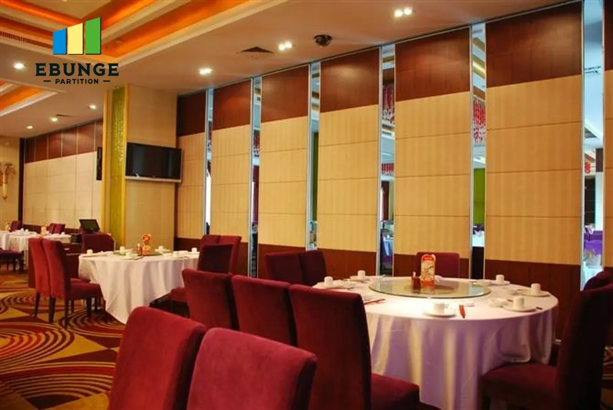
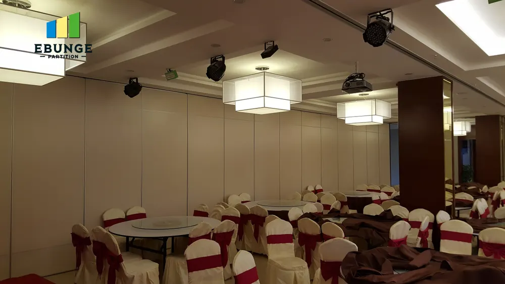
EBUNGE movable wall panels are individually movable and suspended from a top track. They cross the opening without a floor track, so the floor line stays clear during a changeover. That confirmed behaviour shapes the map: the overhead route becomes the critical line to draw, and the floor plan becomes the space the panels must not obstruct.
- Opening line: the full extent the panels must cover when the room is divided.
- Movement route: the path each panel follows between the opening and its parking position.
- Stacking position: the planned place where panels park when the room is open.
- Route type: straight, turning or stacking, as reviewed from the layout.
- Open questions: items that need drawing review, site verification or specialist input.
Step One: Fix the Room Schedule Before the Route
Coordination scope: load map.
Changeover planning fails when the room schedule is vague. Before drawing a single route, list each space, how it is used across a typical week, and which combinations of rooms must be possible. A ballroom that splits into three, a training room that pairs with a breakout area, or a hall that opens for exhibitions all produce different route demands.
Named venues are examples only. The same method applies to hotels, schools, offices, conference centres and renovation projects wherever flexible division is required. What matters is that the schedule is written down and agreed by the people who will actually operate the space.
Separate daily use from occasional use
Mark which changeovers happen often and which happen rarely. The exact overhead route and support arrangement must be confirmed by the responsible project team from coordinated drawings.
Step Two: Draw Straight, Turning and Stacking Routes
Every proposed movement path needs a continuous connected overhead route. The exact route, junction arrangement, continuous overhead path and parking position must be confirmed from the coordinated project drawings. Where the layout turns a corner, show the turn and flag it for review.
- Trace the opening line on the current architectural layout.
- Draw the overhead route from the opening to the planned stacking position.
- Mark each turn, junction and change of direction.
- Shade the floor area the panels pass over, so adjacent uses are visible.
- Note any obstruction, column, ceiling feature or service that the route appears to meet.
- Send the marked layout for project-specific review before specification is fixed.
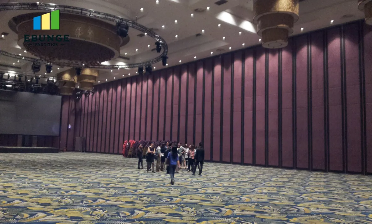
Parking style is customised to the customer layout and project requirements, and compact stacking may be possible when the coordinated design permits it. The map should state the intended parking arrangement and leave the engineering confirmation to the drawing review.
Step Three: Build the Changeover Load Table
A load map becomes useful when it is paired with a simple table that links each room state to its route and parking condition. The table below is a template, not a performance statement; fill it from the agreed schedule and the reviewed layout.
| Room state | Panels in use | Route drawn | Parking position | Open item |
|---|---|---|---|---|
| Fully open | None | Not applicable | Stacked at planned position | Confirm stack footprint |
| Two-room split | Partial set | Straight or turning, per layout | Remainder parked | Confirm route continuity |
| Full division | Full set | Full route to opening | Stack empty | Confirm pass-door need |
Keep the table on the same sheet as the drawing, or cross-reference sheet numbers. A table that lives apart from the layout tends to drift out of date.
Step Four: Coordinate Finishes, Seals and Acoustic Expectations
Confirmed finish options include laminate, melamine, fabric, leather, glass and other approved surfaces. Record the intended finish per face and per room so the specification and the visual schedule stay aligned.
Seals and acoustic concepts can be described generically at planning stage. Instead, state the acoustic requirement, note that it needs project-specific confirmation, and keep the claim tied to documented evidence for that project.
Evidence note: a finish sample, photograph or drawing shows appearance and intent only. It does not demonstrate acoustic performance, structural capacity, fire behaviour or cleaning compatibility. Those require matching project documentation.
Step Five: Plan Pass Doors and Everyday Operation
Pass-door requirements belong on the map early, because a door position changes how people move during a changeover and how the room is used when closed. Discuss pass-door requirements with the supplier and record the agreed arrangement on the layout.
Also record who needs to see the map. Facility teams need the parking position and the clear floor line. Contractors need the route and the review items. Designers need the finish schedule. Owners need a plain statement of what is confirmed and what is still open.
Keep a visible evidence boundary
Label every item on the map as confirmed, to be reviewed, or supplied by others. This single habit prevents a planning sketch from being read as an engineering approval, and it keeps the project resources and drawing set consistent as the design develops.
Common Coordination Gaps to Catch Early
- Stacking positions shown without checking the surrounding floor use.
- Finish schedules that conflict with the room-by-room visual intent.
- Acoustic expectations written as promises rather than requirements to confirm.
- Pass doors added late, forcing the route to be redrawn.
Review the map against the movable wall product information and the current architectural set, then log every change with a date and a responsible person.
Frequently Asked Questions
What exactly is a facility partition changeover load map?
It is a planning drawing and table that records how movable panels move between the opening and their parking position, which routes are straight, turning or stacking, and which items still need project-specific review.
Do movable partitions need a floor track for the changeover route?
EBUNGE movable wall panels are top-hung and cross the opening without a floor track or floor hardware along the partition line. The route still needs a continuous connected overhead path, which the map must show and the project review must confirm.
Can the map specify acoustic performance?
It can record the acoustic requirement and note that it needs project-specific confirmation. Visible references can support layout discussion but do not verify hidden construction or performance.
Which finishes should appear on the map?
Record the intended finish per face using the confirmed options: laminate, melamine, fabric, leather, glass and other approved surfaces. Finish selection is a visual and specification decision; it does not by itself evidence performance.
When should pass doors be discussed?
Early, before routes are fixed. Pass-door requirements and project documentation can be discussed with the supplier, and the agreed arrangement should be drawn on the layout so the route and the room use stay consistent.
Who should approve the finished map?
The project team should agree a named reviewer for routes, stacking and support questions, with the owner or operator confirming the room schedule. Confirm project-specific support, acoustic and dimensional requirements before specification is finalised.
Conclusion and Next Step
A facility partition changeover load map works when it stays honest: confirmed product behaviour on one side, open project questions on the other. Draw the routes, mark the parking positions, record the finishes, and label every assumption for review. Then confirm project-specific support, acoustic and dimensional requirements with the people who hold the evidence.
Ready to review your layout? Contact the EBUNGE team to discuss routes, stacking positions, pass doors and the documentation your project needs.